 Skip to content
 In the face of rapidly advancing technology and evolving industry standards, we found that a clear, concise, and accessible guide on sheet metal design was needed. We want to bridge the knowledge gap and empower everyone, from industry professionals to amateur enthusiasts, with the practical know-how to create effective and efficient designs.
That’s why we put together this blog post. In this guide, we delve into the principles of sheet metal design, provide technical insights, and share essential guidelines to help you navigate the world of sheet metal fabrication with confidence. Let’s get started!

1. Basic on Sheet Metal Fabrication
What is Sheet Metal Fabrication?
Sheet metal fabrication is a highly versatile process used in the manufacturing industry to create various parts and components. This process involves cutting, forming, and assembling metal into different shapes and structures
The Procedure of Creating Parts from Metal Sheets
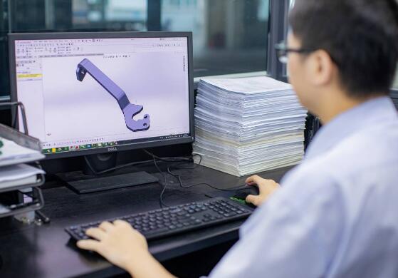
The first step in creating a sheet metal part is sheet metal design. This process starts with an idea or concept that is then turned into a detailed 3D model using Computer-Aided Design (CAD) software. This 3D model includes all the necessary details such as the size, shape, material, and any features or elements that the final part will have.
After the design phase, the sheet metal is then cut and formed to match the specifications laid out in the design. The cutting process can be done using various methods, including laser cutting, plasma cutting, or waterjet cutting. The forming process, on the other hand, can involve metal stamping, progressive die stamping, deep draw stamping, or fourslide stamping.
The Benefits of Employing Sheet Metal Components
Employing sheet metal components offers numerous benefits in various applications. These components are incredibly versatile, durable, and cost-effective. With proper design and manufacturing, sheet metal components can withstand high stresses, making them ideal for various industries such as automotive, aerospace, and construction.
Moreover, sheet metal fabrication allows for high-volume production, making it an economical option for creating a large number of parts. With modern machinery and technology, precise and complex shapes can be achieved, enhancing the functionality and aesthetic appeal of the final product.
2. Basics of Forming
Bending (Press Brake)
Forming is a key aspect of sheet metal design. One of the most common methods in sheet metal forming is bending, a process that modifies the shape of sheet metal by applying force to it, causing it to bend at an angle and form the desired shape. The bending process is primarily done using a tool known as a press brake.
A press brake is a machine pressing tool for bending sheet and plate material, most commonly sheet metal. It forms predetermined bends by clamping the workpiece between a matching punch and die. This tool allows for a high degree of precision, with the ability to create intricate and complex shapes as required in the sheet metal design.

In operation, the sheet metal workpiece is positioned over the die block. The punch is then driven down into the die space, bending the sheet metal to the angle of the die. In a typical scenario, the punch and die are custom-designed to perform specific operations.
Press brakes come in mechanical and hydraulic types.
- Hydraulic press brakes are more common due to their power, precision, and flexibility.
- CNC press brakes (Computer numerical control) provide even more accuracy and efficiency, allowing for precise control over the depth and pressure of the punch.
Vital Parameters in Bending
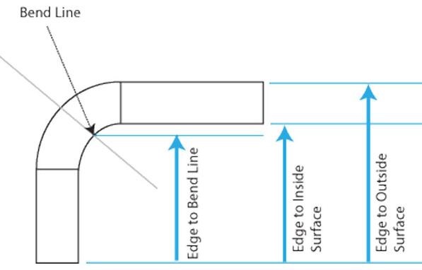
1. Bend Line refers to the line along which the sheet metal bends.
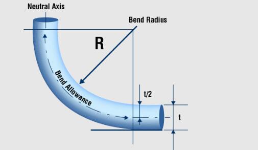
2. Bend Radius is the radius of the rounded portion that connects the two legs of a bend. It is measured to the centerline of the bend.
3.Bend Angle is the angle of the bend, measured between the original flat sheet and the bent section. The angle is crucial in determining how the finished product fits together with other parts.
4.Neutral Axis is the part of the material that does not change its length during the bending process.
5. K-Factor is a ratio that represents the location of the neutral axis with the thickness of the sheet metal.
6. Bend Allowance is the length of the neutral line between the bend lines, or in other words, the arc length of the bend. It is used to calculate the length of the flat blank sheet metal necessary to create a bent part without any deformation.
The Significance of K-Factor in Sheet Metal Design
In the realm of sheet metal design, the K-Factor holds significant importance. It’s a constant used to calculate the sheet metal’s bend allowance, informing the flat layout dimensions necessary to achieve a desired bent part. Essentially, K-Factor is a ratio that represents the location of the neutral axis within the thickness of the sheet metal.
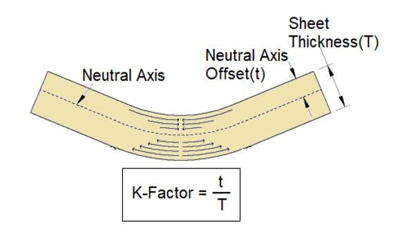
The K-Factor value ranges between 0 and 0.5. A K-Factor of 0 indicates that the neutral axis is at the inside surface, while a K-Factor of 0.5 suggests that the neutral axis is at the middle of the material.
Bend Relief
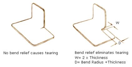
Bend relief is a notch added to the end of a bend to avoid tearing or cracking in the material. In essence, it gives the material some “relief” from the stress of bending. The dimensions of the bend relief are usually specified by the sheet metal designer and can depend on the material type and thickness. Precise bend relief ensures a more effective and efficient bending process while maintaining the quality of the material.
Bend Height
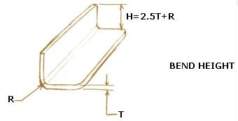
Bend height is the distance from the inside surface of the bend to the original plane of the sheet metal. It’s an important factor to consider when planning your sheet metal design as it impacts both the functionality and aesthetics of the finished product.
Forming Near Holes
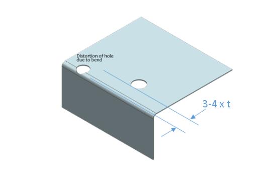
Forming near holes can be a tricky process. When a hole is too close to a bend, the deformation that occurs during bending can distort the hole. Generally, the center of any hole should be at least 1.5 times the material thickness away from the start of a bend to avoid distortion.
Smallest Hole Diameter
When it comes to smallest hole diameter, in most cases, the minimum diameter should not be less than the material thickness for best practices. If the hole’s diameter is less than the material thickness, it could lead to issues during manufacturing like tearing or distortion.
3.Basic of Laser Cutting
What is Laser Cutting?

Laser cutting is a non-contact, thermal-based fabrication process suitable for cutting and etching various materials, including metal. It works by directing a high-power laser beam at the material to be cut. The heat from the laser beam is so intense that it causes the material to melt or vaporize, creating a precise cut.
Laser cutting is known for its high accuracy and repeatability. It’s commonly used in industries such as automotive, aerospace, electronics, and many more due to its precision and versatility. For a deeper understanding of the laser cutting process, refer to our laser cutting page.
Pros and Cons of Using Laser Cutting
Pros of Laser Cutting:
- High Precision: Laser cutting offers high precision and accuracy, enabling the creation of complex and intricate designs that are difficult to achieve with other cutting methods.
- Fast Processing Time: Laser cutting is usually quicker than other traditional cutting techniques, especially when dealing with complex designs or high-volume projects.
- Versatility: Laser cutting can be used on a wide variety of materials, including steel, stainless steel, aluminum, and more.
- Non-Contact Process: Since laser cutting is a non-contact process, it reduces the risk of material contamination and mechanical wear.
Cons of Laser Cutting:
- High Energy Consumption: Laser cutting machines typically use a significant amount of power, which may be a concern in terms of operational costs and environmental impact.
- Limited Material Thickness: Laser cutting may not be the best option for extremely thick materials as the cutting efficiency decreases with the increase in material thickness.
- Heat Affected Zone (HAZ): The high temperatures involved in laser cutting can alter the material’s properties in the surrounding area, known as the Heat Affected Zone.
Precision Levels in Laser Cutting-Tolerance
The precision of laser cutting is usually measured in terms of the tolerance level it can achieve. High-end laser cutting machines can maintain a tolerance level of around 10 micrometers (0.0004 inches).
Limitations on Materials and Suitable Substances
Laser cutting is extremely versatile and can be used to cut a variety of materials. However, it does have some limitations in terms of the materials it can process effectively. For example, metals like aluminum and stainless steel are ideal for laser cutting because they respond well to the process and can be cut precisely.
Other materials, such as copper and brass, can also be laser cut, but they are more challenging due to their high reflectivity and thermal conductivity. Bronze, on the other hand, is generally not recommended for laser cutting as it may cause issues due to its composition. Glass and certain types of plastic may not be suitable for laser cutting because they can reflect or refract the laser light, which can cause damage to the machine or lead to inaccurate cuts.
Local Hardening and Warping
As the laser cutting process involves generating high heat to cut through materials, it can lead to local hardening. This phenomenon occurs when the intense heat from the laser alters the material’s structure near the cut, causing it to harden. This effect is more pronounced in certain metals like steel and stainless steel.
The heat can also cause thermal warping, a distortion in the material’s shape due to uneven heating and cooling. However, the advanced laser cutting machines equipped with effective cooling systems can manage these effects and keep them to a minimum.
Kerf and Gaps for Apertures and Channels
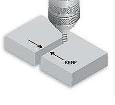
In laser cutting, a small portion of the material is burned away, resulting in a gap known as the laser kerf. This gap generally ranges from 0.08mm to 0.45mm, depending on factors like material type, thickness, and other conditional factors.
When designing parts, it’s critical to keep in mind the size of the laser kerf. To avoid crossover cutting, a minimum gap of 1-2mm should be left between the parts. For the same reason, parts should also be kept 2-5mm away from the edge of the material. This is because sheets may be warped or slightly off in their sizing, and using the sheet edges as a border could lead to inaccurate cuts.
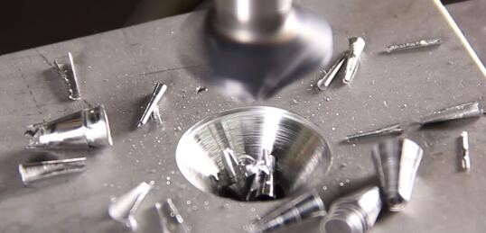
4.Manufactured and Molded Countersinks
Countersinks are an integral part of sheet metal design. They are recessed areas that enable screws and other fasteners to fit flush with the surface, providing both aesthetic appeal and functional utility. While designing these elements, we must consider the two primary ways they’re produced: manufacturing and molding.
Manufactured countersinks are typically created using a specialized drill bit that cuts a conical hole into the material. When designing for this method, we should adhere to the following guidelines:
- The diameter of the countersink should ideally match the diameter of the screw head. This ensures a snug fit and a neat appearance.
- For countersinks intended for flat-head screws, the angle of the countersink should match the angle of the screw head, typically 82 degrees in North America.
- In terms of depth, the countersink should be no deeper than necessary to accommodate the intended fastener. Overly deep countersinks can weaken the surrounding metal.
Molded countersinks, on the other hand, are formed during the metal stamping process, where a die punches out the desired countersink shape. When designing for molded countersinks, keep these guidelines in mind:
- Due to the force involved in the stamping process, be sure to consider the thickness of the material when designing the countersink. Thicker materials can withstand higher forces, allowing for deeper or more intricate countersinks.
- When designing the die, ensure that its dimensions precisely match the desired final outcome, as the stamping process doesn’t allow for much post-production modification.
- Unlike manufactured countersinks, molded countersinks can be formed in a variety of complex shapes. Make sure to leverage this advantage when it is beneficial to your design.
Countersink Precision Measurements
While designing countersinks, precision is of utmost importance. For a proper fit, the countersink’s measurements must align with those of the intended fastener. Here are some key guidelines for achieving high precision:
- As a rule of thumb, the diameter of the countersink should match the head diameter of the screw. If the diameter is too large, the screw head may not sit flush with the surface, whereas if it’s too small, the screw head may not fit at all.
- Countersink depth is another crucial factor. The depth must be sufficient to allow the screw head to sit flush with the surface of the material, but not so deep that it weakens the material around it. Consider the strength and thickness of the material in your design.
- The angle of the countersink should match the angle under the screw head. A common standard for many screws is an 82-degree angle.
Dimensions of Countersinks
The dimensions of a countersink can greatly influence the fit and finish of the assembled part. Here are some guidelines to consider:
- The diameter of the countersink should ideally be 10% larger than the screw head diameter. This gives some margin for alignment errors during assembly.
- The depth of the countersink should be such that the screw head sits slightly below the surface of the material.
Aspects of Notches and Tabs
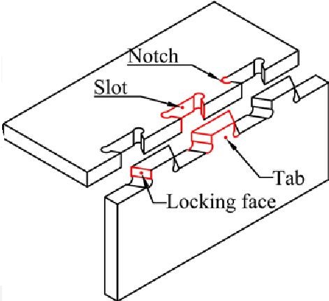
- Notches should be designed with their lengths greater than their width. A length-to-width ratio of 2:1 or more is recommended to avoid tearing or warping during the fabrication process. Also, the width of the notch should be at least equal to the thickness of the material to ensure structural stability.
- Tabs are often used in sheet metal design to align or join parts together. The width of a tab should be at least two times the thickness of the material for stability. The length of a tab should be designed to be as short as possible while still providing sufficient surface area for the intended connection.
Suggestions for Notch Designing
- Aim to keep notch corners as square as possible. Avoid sharp, pointed corners as these can become stress points and lead to cracking. In certain cases, you might consider using a small radius to reduce stress.
- Maintain a minimum distance between notches. This distance should ideally be at least two times the thickness of the material. Closer notches might lead to the material tearing during the fabrication process.
5.Rounded Corners
Rounded corners play a crucial role in sheet metal design. The primary purpose of these is to eliminate sharp edges that can pose safety risks and induce stress concentrations, leading to potential fractures. Here are some guidelines to consider:
- The radius of the rounded corners should be at least equal to the material’s thickness to maintain the structural integrity of the design. Larger radii can further reduce stress concentrations and are encouraged for parts that will be under significant stress or strain.
- Be mindful of the fabrication method being used. For instance, laser cutting can produce precise rounded corners but might require specific considerations for kerf width and heat-affected zones.
- Rounded corners can also make the part more aesthetically pleasing, which can be a crucial factor in industries like music and aerospace, where both functionality and appearance are essential.
6.Cut-Outs for Relief
Cut-outs in sheet metal are often used for functional reasons, such as fitting components together or reducing weight. However, they can also provide relief in bending areas, reducing stress and potential deformation. Here are some guidelines:
- The size and shape of the cut-outs should take into consideration the expected stresses and strains in the part. A good rule of thumb is to make cut-outs as small and as few as possible while still fulfilling their purpose.
- Keep the distance between cut-outs at least two times the material’s thickness to avoid compromising the part’s structural integrity.
- Similar to rounded corners, the fabrication method can influence the design of cut-outs. Techniques like plasma cutting or waterjet cutting offer different advantages and constraints that should be factored into the design process.
7.Conclusion
In conclusion, understanding the basics of sheet metal fabrication and the process involved in forming and laser cutting are crucial steps in creating effective designs.By adhering to these sheet metal design guidelines, engineers and designers can successfully navigate the process of turning raw sheets into valuable components.
If you are interested in learning more about sheet metal design or looking for expert assistance, explore wipunch.com, your comprehensive resource on sheet metal design and fabrication. Our in-depth guides and services are tailored to help you deliver top-notch sheet metal components. Reach out today to find out how we can support your project’s success.
8.FAQ
How is the K-Factor important in sheet metal design?
The K-Factor in sheet metal design is a ratio that represents the location of the neutral axis with respect to the thickness of the sheet metal. An accurate K-Factor is crucial for predicting the amount of stretch or compression of the material during bending, ensuring accurate part creation.
What factors should be considered when designing countersink holes and tabs in sheet metal?
When designing countersinks and tabs, factors such as the precision of the countersink measurements, the dimensions, and the appropriate notch design should be considered. It’s crucial to follow the guidelines for minimum material thickness and distances between features to ensure the integrity of the design.
